ESP32 Camera

ESP32 CAM est un module équipé d’une camera. Grâce à un programme chargé, elle permet de diffuser un flux video sur un réseau.
Programmer le module
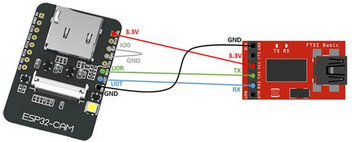
La carte n’a pas de connecteur USB. Il faut donc brancher un module FTDI qui fera le lien : 2 fils d’alimentation (+ et -), 2 fils de transfert (Rx et Tx)
Pour que le module puisse recevoir le programme, la broche IO0 doit être reliée à la masse.

Si le programme ne se télécharge pas, essayer avec du 5V sur la broche 5V.
Programmer avec l’IDE Arduino
Pour que la carte soit reconnue, pour avoir les bibliothèques et compiler le programme, il faut ajouter une URL dans le gestionnaire de carte :
https://dl.espressif.com/dl/package_esp32_index.jsonInstaller ensuite « Esp32 by Expressif Systems »
Le programme
Le programme est dans les exemples ou sur Github. Renseigner les SSID et MdP du réseau Wifi :
#include "esp_camera.h"
#include <WiFi.h>

//
// WARNING!!! Make sure that you have either selected ESP32 Wrover Module,
//            or another board which has PSRAM enabled
//

// Select camera model
//#define CAMERA_MODEL_WROVER_KIT
//#define CAMERA_MODEL_M5STACK_PSRAM
#define CAMERA_MODEL_AI_THINKER

const char* ssid = "XXXX";
const char* password = "XXXX";


#if defined(CAMERA_MODEL_WROVER_KIT)
#define PWDN_GPIO_NUM    -1
#define RESET_GPIO_NUM   -1
#define XCLK_GPIO_NUM    21
#define SIOD_GPIO_NUM    26
#define SIOC_GPIO_NUM    27
#define Y9_GPIO_NUM      35
#define Y8_GPIO_NUM      34
#define Y7_GPIO_NUM      39
#define Y6_GPIO_NUM      36
#define Y5_GPIO_NUM      19
#define Y4_GPIO_NUM      18
#define Y3_GPIO_NUM       5
#define Y2_GPIO_NUM       4
#define VSYNC_GPIO_NUM   25
#define HREF_GPIO_NUM    23
#define PCLK_GPIO_NUM    22

#elif defined(CAMERA_MODEL_M5STACK_PSRAM)
#define PWDN_GPIO_NUM     -1
#define RESET_GPIO_NUM    15
#define XCLK_GPIO_NUM     27
#define SIOD_GPIO_NUM     25
#define SIOC_GPIO_NUM     23

#define Y9_GPIO_NUM       19
#define Y8_GPIO_NUM       36
#define Y7_GPIO_NUM       18
#define Y6_GPIO_NUM       39
#define Y5_GPIO_NUM        5
#define Y4_GPIO_NUM       34
#define Y3_GPIO_NUM       35
#define Y2_GPIO_NUM       32
#define VSYNC_GPIO_NUM    22
#define HREF_GPIO_NUM     26
#define PCLK_GPIO_NUM     21

#elif defined(CAMERA_MODEL_AI_THINKER)
#define PWDN_GPIO_NUM     32
#define RESET_GPIO_NUM    -1
#define XCLK_GPIO_NUM      0
#define SIOD_GPIO_NUM     26
#define SIOC_GPIO_NUM     27

#define Y9_GPIO_NUM       35
#define Y8_GPIO_NUM       34
#define Y7_GPIO_NUM       39
#define Y6_GPIO_NUM       36
#define Y5_GPIO_NUM       21
#define Y4_GPIO_NUM       19
#define Y3_GPIO_NUM       18
#define Y2_GPIO_NUM        5
#define VSYNC_GPIO_NUM    25
#define HREF_GPIO_NUM     23
#define PCLK_GPIO_NUM     22

#else
#error "Camera model not selected"
#endif

void startCameraServer();

void setup() {
  Serial.begin(115200);
  Serial.setDebugOutput(true);
  Serial.println();

  camera_config_t config;
  config.ledc_channel = LEDC_CHANNEL_0;
  config.ledc_timer = LEDC_TIMER_0;
  config.pin_d0 = Y2_GPIO_NUM;
  config.pin_d1 = Y3_GPIO_NUM;
  config.pin_d2 = Y4_GPIO_NUM;
  config.pin_d3 = Y5_GPIO_NUM;
  config.pin_d4 = Y6_GPIO_NUM;
  config.pin_d5 = Y7_GPIO_NUM;
  config.pin_d6 = Y8_GPIO_NUM;
  config.pin_d7 = Y9_GPIO_NUM;
  config.pin_xclk = XCLK_GPIO_NUM;
  config.pin_pclk = PCLK_GPIO_NUM;
  config.pin_vsync = VSYNC_GPIO_NUM;
  config.pin_href = HREF_GPIO_NUM;
  config.pin_sscb_sda = SIOD_GPIO_NUM;
  config.pin_sscb_scl = SIOC_GPIO_NUM;
  config.pin_pwdn = PWDN_GPIO_NUM;
  config.pin_reset = RESET_GPIO_NUM;
  config.xclk_freq_hz = 20000000;
  config.pixel_format = PIXFORMAT_JPEG;
  //init with high specs to pre-allocate larger buffers
  if(psramFound()){
    config.frame_size = FRAMESIZE_UXGA;
    config.jpeg_quality = 10;
    config.fb_count = 2;
  } else {
    config.frame_size = FRAMESIZE_SVGA;
    config.jpeg_quality = 12;
    config.fb_count = 1;
  }

  // camera init
  esp_err_t err = esp_camera_init(&config);
  if (err != ESP_OK) {
    Serial.printf("Camera init failed with error 0x%x", err);
    return;
  }

  //drop down frame size for higher initial frame rate
  sensor_t * s = esp_camera_sensor_get();
  s->set_framesize(s, FRAMESIZE_QVGA);

  WiFi.begin(ssid, password);

  while (WiFi.status() != WL_CONNECTED) {
    delay(500);
    Serial.print(".");
  }
  Serial.println("");
  Serial.println("WiFi connected");

  startCameraServer();

  Serial.print("Camera Ready! Use 'http://");
  Serial.print(WiFi.localIP());
  Serial.println("' to connect");
}

void loop() {
  // put your main code here, to run repeatedly:
  delay(10000);
}
Si vous avez des problèmes :
https://randomnerdtutorials.com/esp32-cam-video-streaming-face-recognition-arduino-ide/
https://randomnerdtutorials.com/esp32-cam-troubleshooting-guide/
Visualisez !
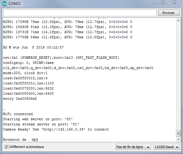
Relever l’adresse IP du module.

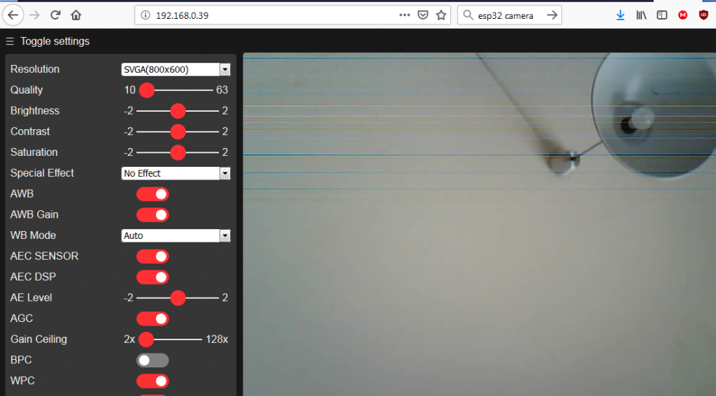
Il n’y a plus qu’à regarder :
